製品説明
China Low price High Speed Ladder type cable tray roll forming machine
cable tray system is used to support insulated electrical cables used for power distribution, control, and communication. Cable trays are used as an alternative to open wiring or electrical conduit systems, and are commonly used for cable management in commercial and industrial construction
cable tray making machines,cable tray roll forming machine,Cable Tray Production Line make different sizes of cable tray, for example cable tray width from 100-800mm, height from 50-200mm. it is easy to change size by moving whole line rollers and cut blade positions.
Process of cable tray forming machines:
decoiler material-leveling-punch-cutting-powered transmission table-forming
Main features of cable forming machines
suitable material thickness 0.8-2.5mm
gearbox move the cable tray lines
roller material CR12 mould
solid shaft diameter 80mm
punch capicity 25T x 2
machine weight about 40 ton
Decoiler
5 Tons hydraulic Decoiler,material width <= 1250mm, inner coil <= 480-520mm,outter diameter coil <= 1500mm.
Material Feeding Xihu (West Lake) Dis.
1. Positioning plate: Adjust the position of both ends to makt it fit the width of the feeding.
2.Xihu (West Lake) Dis. frame: Play a role in supporting the transport of the matrial roll
3. Xihu (West Lake) Dis. roller:The upper and lower round rollers are designed to make the feeding process more smooth.
Leveling Device1.leveling roller upper 5 roller,down 4 rollers
2. Leveling roller diameter: 100mm
3.Material: 40Cr heat treatment, electroplating
4.Motor Power: 7.5kw
5.Leveling speed: 12m/min
Punching Part
1.Hydraulic punching, all holes required for punching profiles at 1 time, adjustable punching row spacing
2.Cylinder: 25ton x 2
3.Hydraulic power: 11kw
4.Die Material:Cr12 Mov heat treatment HRC5-62,Two dies
5. Punching accuracy:+ – 1 mm
6. Type-changing method: the screw rod adjusts the position of the left and right oil cylinders,and the left and right hole row spacing
can be adjusted
Hydraulic pre-cutting
1.Hydraulic front shearing,stop cutting,no waste
2.Cylinder: 15 tons
3.Blade material; Cr12 Heat treatment HRC58-62
powered transmission table
1.Power flat roll, motor drive, screw width adjustment
2.Length 6 mtrs
3.Flat roll size: Φ60mm, 45# steel surface electroplating
4.Motor power: 1.5 kw
Main Roll Forming Mill
1.Automatic continuous roll forming, manual + automatic control, motor drive, stepless adjustment in the range of width 100-800, height 50-200, electric control to adjust the above parameters
2.Forming material: ordinary cold-rolled sheet and galvanized sheet below 350Mpa
3.Working range: feed width 1200mm, material thickness 1.0-2.0mm
4.Roller stations: 26 stations
5.Motor Power:5.5+4 kw
6.Transmission mode: gear, sprocket
7.Shaft Diameter: 80mm,45# steel
8.Roller material: 40Cr heat treatment HRC55-60, hard chrome plating on the surface
9.Forming frame: H400 section steel welded with 25mm table top, the whole is shot blasted and sanded to remove rust. Multi-hole gantry milling machine table and connection port.
10:Wall panel: 25mm thick iron plate, plasma cutting nitrogen cooling to ensure straightness ±1mm, surface shot blasting and sanding to remove rust, 5m CNC gantry milling to process the appearance, bearing holes and bearing slip.
11.Forming Speed:12m/min
12.Adjustment method: The display screen sets the profile parameters, the computer automatically adjusts the distance between the left and right
roll groups, and the motor drives
13:Adjusting motor power: 2.2kw x 2
Product Features
1. More efficient and accurate execution of production orders;
2. High equipment reliability;
3. Little waste of materials and energy;
4. High productivity;
5. High quality materials, get a longer service life;
6. All parts of the machine are processed with precision, and the surface of the roll is chromeplated to ensure that customers can
get qualified products at the same time, it can avoid the scratch of the color steel surface paint, and increase the service life of the roll;
7. Customized coil processing solutions to solve all aspects of technical problems.
Why choose Us?
- We have sold more than 3000 sets roll forming machines to many countries around the world.
- We have hundreds of models about all kinds of roll forming machine for your reference, you could’t worry if you don’t have a profile drawing.We can recommond you some classical models that is common in your country.
- When designing the machine, our considerate service will estimate and avoid the problem that may happen.
- One set machine can provide many solutions with different price level.But they are all the cost-effective.
- We attach importance to many details. Every machine part quality is higher than our competitors in same price level.
| After-sales Service: | Online Support, Free Spare Parts |
|---|---|
| Warranty: | 12 Months |
| Certification: | CE, ISO9001 |
| Customized: | Customized |
| Condition: | New |
| Control Type: | CNC |
| サンプル: |
US$ 110000/Set
1 Set(Min.Order) | |
|---|
| カスタマイズ: |
利用可能
| カスタマイズされたリクエスト |
|---|

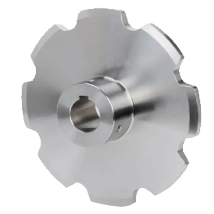
コンベア運転中にラダースプロケットの摩耗や損傷を防ぐにはどうすればよいですか?
コンベヤ運転中にラダースプロケットの摩耗や損傷を防ぐことは、スプロケットの寿命を延ばし、コンベヤシステム全体の効率を維持するために不可欠です。以下に、予防策をいくつか示します。
- 適切な潤滑: 梯子スプロケットとコンベヤチェーンには、適切な潤滑剤を定期的に塗布してください。潤滑により、スプロケットの歯とチェーンリンク間の摩擦が軽減され、摩耗が最小限に抑えられ、スプロケットの寿命が延びます。
- チェーンの張力: コンベヤチェーンの張力を適切に保つことが重要です。適切な張力調整は、ラダースプロケットやチェーンリンクへの過度の負荷を防ぎ、摩耗を軽減し、早期故障を防止します。
- チェーンアライメント: コンベアチェーンがラダースプロケットと正しく位置合わせされていることを確認してください。位置ずれはスプロケットの歯とチェーンリンクの摩耗を不均一にし、摩耗の加速や損傷につながる可能性があります。
- 清潔さ: ラダースプロケットとその周辺は、ゴミ、汚れ、異物などが付着しないよう清潔に保ってください。異物が付着すると、チェーンの詰まり、摩耗の加速、スプロケットの性能低下の原因となります。
- 定期点検: ラダースプロケットの摩耗、損傷、変形などの兆候がないか、定期的に目視点検を行ってください。問題の早期発見は、タイムリーなメンテナンスを可能にし、さらなる損傷を防ぎます。
- 摩耗したスプロケットを交換する: ラダースプロケットの歯の状態を定期的に監視してください。スプロケットの歯に著しい摩耗、欠け、または変形が見られる場合は、コンベヤチェーンへのさらなる損傷を防ぐため、速やかにスプロケットを交換してください。
- チェーンの摩耗状態を点検する: コンベアチェーンに摩耗、伸び、または伸長の兆候がないか定期的に点検してください。摩耗したチェーンはスプロケットの摩耗を加速させる可能性があるため、推奨耐用年数を超えている場合はチェーンを交換してください。
- 耐荷重: ラダースプロケットは、コンベアシステムの耐荷重能力に適したサイズと定格であることを確認してください。小さすぎるスプロケットや、重荷重用途向けに設計されていないスプロケットを使用すると、早期摩耗や故障の原因となります。
- 製造元のガイドラインに従ってください。 ラダースプロケットの製造元が推奨するメンテナンス手順とサービス間隔を遵守してください。製造元によっては、スプロケットの性能と寿命を最適化するために、潤滑、張力調整、点検に関する具体的なガイドラインを提供している場合があります。
これらの予防措置を講じることで、ラダースプロケットの摩耗や損傷を最小限に抑え、耐用年数を延ばし、信頼性と効率性に優れたコンベヤシステムを維持できます。定期的なメンテナンスと点検は、潜在的な問題を早期に発見して対処し、高額なダウンタイムを防ぎ、コンベヤシステムの円滑な稼働を確保するために不可欠です。
How do I Calculate the Required Torque and Power for a Ladder Sprocket Setup?
Calculating the required torque and power for a ladder sprocket setup involves considering several factors related to the conveyor system’s design and operation. Here’s a step-by-step guide to the calculation process:
- Identify Parameters: Gather the necessary data, including conveyor system specifications such as conveyor length, speed, chain pitch, sprocket diameter, and the weight of the conveyed material per unit length (if applicable).
- Calculate Chain Tension: Determine the chain tension in the conveyor system. Chain tension depends on the conveyor’s angle of inclination, the weight of the material being conveyed, and any additional forces acting on the chain.
- Calculate Chain Pull Force: The chain pull force is the force required to move the conveyor chain. It is calculated by multiplying the chain tension by the number of chain strands.
- Calculate Torque: To calculate the torque required for the ladder sprocket, multiply the chain pull force by the sprocket radius. The sprocket radius is half of the sprocket diameter.
- Consider Efficiency: Take into account the efficiency of the conveyor system. The actual torque required will be higher than the calculated torque due to efficiency losses in bearings, chains, and other components.
- Calculate Power: To determine the power required for the ladder sprocket setup, multiply the calculated torque by the conveyor’s rotational speed in radians per second. The rotational speed can be obtained by converting the conveyor speed from meters per second to radians per second.
- Apply Safety Factors: Apply safety factors to the calculated torque and power values to ensure that the system can handle occasional peak loads and avoid running the system at its maximum capacity continuously.
Keep in mind that these calculations provide an estimate of the required torque and power for the ladder sprocket setup. Actual operating conditions, variations in material properties, and other external factors may influence the results. Additionally, it’s essential to consult conveyor system experts or sprocket manufacturers for further guidance and to verify the accuracy of the calculations.
By accurately calculating the required torque and power, you can ensure that the ladder sprocket setup is appropriately sized to handle the conveyor system’s load and operational demands, leading to efficient and reliable conveyor performance.
How do I Choose the Right Size and Pitch of a Ladder Sprocket for my Conveyor System?
Choosing the right size and pitch of a ladder sprocket for your conveyor system is critical to ensure proper operation, efficient power transmission, and prolonged equipment life. Here are the steps to guide you through the selection process:
- 1. Identify Conveyor Chain Type: Determine the type of conveyor chain used in your system. Different chain types have specific pitch measurements, and the ladder sprocket must match the chain’s pitch to ensure proper engagement.
- 2. Determine Sprocket Teeth Count: Calculate the required number of teeth for the ladder sprocket based on the desired conveyor speed, driven shaft RPM, and the chain’s speed factor. The speed factor is typically provided by the chain manufacturer.
- 3. Consider Chain Wrap Angle: Ensure that the sprocket size allows for sufficient chain wrap around the sprocket to prevent chain disengagement. The chain wrap angle should be within the manufacturer’s recommended range.
- 4. Assess Conveyor Load: Evaluate the conveyor system’s load and the maximum tension the chain will experience. The ladder sprocket’s material and design must be able to handle the load without deformation or failure.
- 5. Determine Shaft Diameter: The ladder sprocket’s bore size (inner hole) should match the driven shaft’s diameter or use a taper-lock bushing or through-bore hub to adapt the sprocket to the shaft size.
- 6. Consider Space Constraints: Ensure that the chosen ladder sprocket size fits within the available space in the conveyor system without interfering with other components.
- 7. Consult Manufacturer Data: Refer to the ladder sprocket manufacturer’s data and specifications to find the appropriate sprocket size and pitch options for your specific conveyor chain type.
- 8. Opt for High-Quality Materials: Choose a ladder sprocket made from high-quality materials that offer good wear resistance and durability, especially for applications with harsh environments or heavy loads.
- 9. Seek Expert Advice: If you are unsure about the selection process, consult with conveyor system experts or sprocket manufacturers for assistance in choosing the right ladder sprocket size and pitch.
By carefully considering the chain type, conveyor load, sprocket teeth count, and other relevant factors, you can select the appropriate size and pitch of a ladder sprocket that ensures optimal performance and reliable power transmission in your conveyor system.


editor by CX 2023-10-08


